
01 · LOCATE
Determine pipeline position.
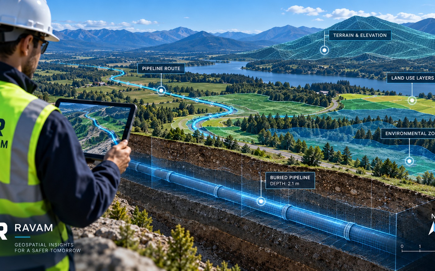
Improve understanding of the buried steel pipeline alignment and route continuity.
A non-contact field program to improve pipeline localization, screen magnetic anomalies, prioritize direct verification and establish the baseline for future monitoring.
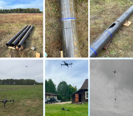
Swamps, flooded areas, deep snow, vegetation and difficult terrain can interrupt conventional field programs. Historic route information may also be incomplete or no longer match present conditions.
Improve understanding of the buried steel pipeline alignment and route continuity.
Map magnetic features associated with pipe sections, joint locations and weld areas.
Identify magnetic signatures and changes that may justify targeted ground verification.
Corridor localization, anomaly screening, route and segment intelligence, comparison between controlled surveys and prioritization of follow-up locations.
A magnetic anomaly is not automatically a confirmed defect. Defect classification and sizing require appropriate field correlation and operator-approved engineering methods.
Every work package begins with the operator's records and decision needs, then builds evidence through controlled acquisition and selected verification.
Review alignment records, construction data, known features, access limits and integrity questions.
Collect repeatable UAV magnetic data and reference measurements under documented conditions.
Apply quality control, correction, georeferencing, mapping and anomaly interpretation.
Compare observations with operator records and appropriate targeted field checks.
Deliver a ranked verification plan and recommendations for the next integrity step.
The payload and reference measurements are configured around the corridor, terrain, safety and repeatability requirements of the work package.
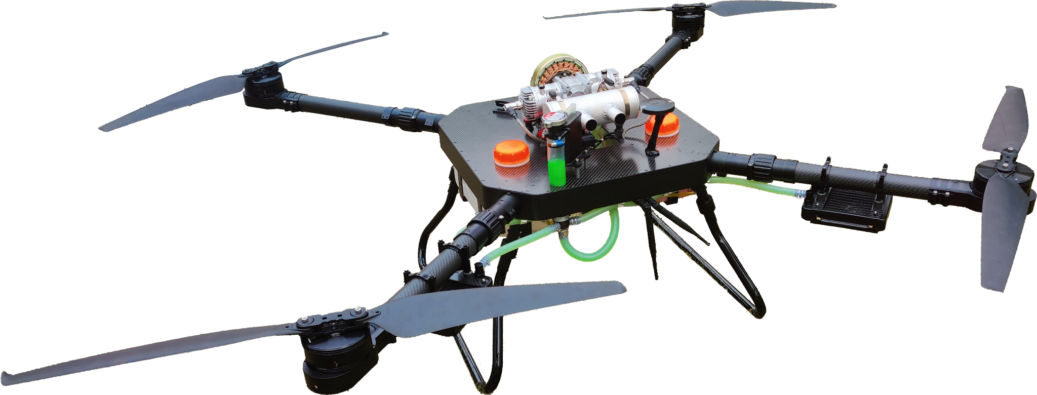
Carries the survey payload along flight lines configured for terrain, safety and repeatability.
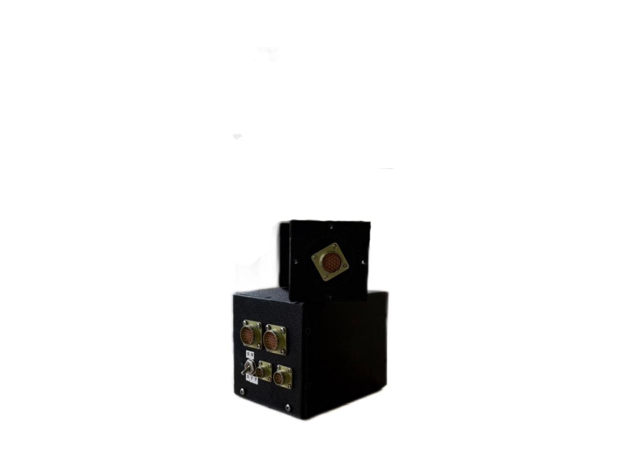
Measures X, Y and Z magnetic-field components and captures directional changes in pipeline response.
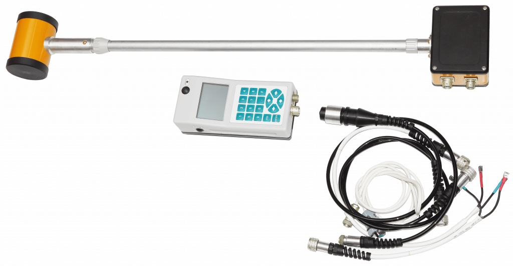
Provides an absolute scalar-field reference for background and consistency checks.
Supports quality control, transformation, anomaly localization and operator-ready reporting.
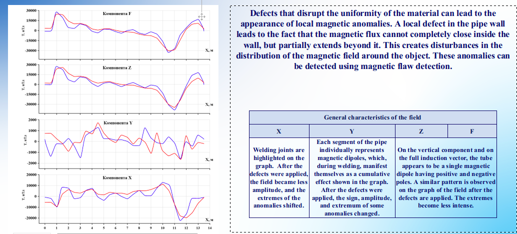
The supplied controlled test data demonstrate measurable magnetic signatures and changes. They support screening methodology development; they do not by themselves establish field defect classification.
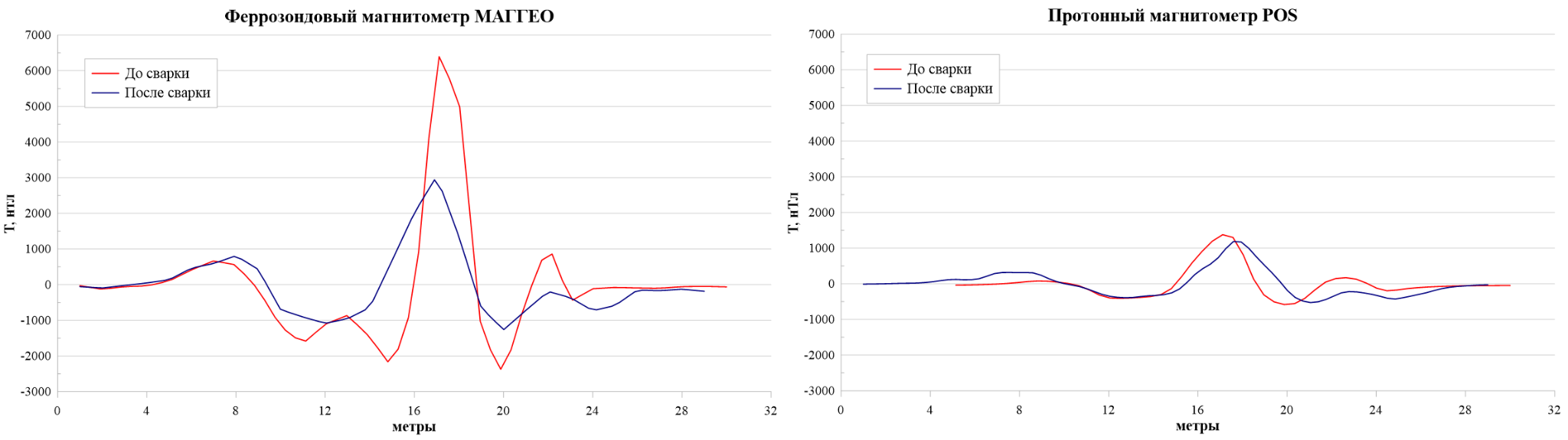
The controlled configuration shows pronounced response around pipe-joint features.
The supplied test reports a reduced anomaly amplitude after the pipe segments were welded.
The proton magnetometer serves a different measurement role in the controlled survey system.
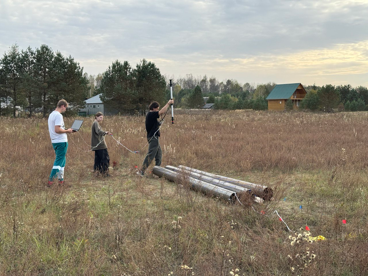
Every campaign documents the conditions that influence magnetic data so later surveys can be compared on a consistent basis.
The survey is delivered as traceable engineering decision support, with method, evidence, confidence and limitations documented.
Verified corridor intelligence can feed a digital twin, enterprise integration and recurring monitoring program without forcing the operator into a predetermined hardware or software configuration.
Agree the verification, acceptance and independent-review pathway for the method.
VIEW ASSURANCE →Add scheduled patrols, NEST infrastructure, multi-sensor observations and operational reporting.
VIEW MONITORING →Connect the corridor baseline to structured asset data, change history and validated analytics.
RAVAM PLATFORM →Start with the available pipeline records, a bounded route section and the integrity decisions the survey must support.